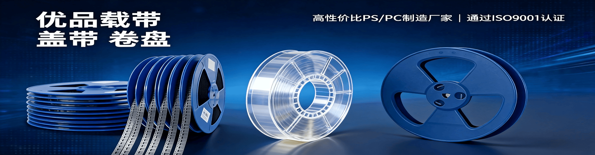
Advantages of PC Carrier Tape in IC Chip SMT Assembly
Kairuie Electronic Materials
1. Introduction
In the SMT (Surface Mount Technology) packaging process, carrier tape serves as a critical material for carrying and protecting electronic components, and its performance directly impacts placement efficiency and product reliability. As IC chips evolve toward miniaturization and higher integration, requirements for carrier tape material, dimensional precision, and electrostatic protection have become increasingly stringent. PC (Polycarbonate) carrier tape, with its excellent mechanical strength, temperature resistance, and dimensional stability, offers unique advantages in IC chip SMT processes. This article systematically analyzes how PC carrier tape enables efficient and stable SMT packaging for IC chips from the perspectives of product structure, process parameters, and quality control.
2. Basic Product Structure and Material Composition
2.1 Layered Structure
PC carrier tape typically adopts a three-layer composite structure:
Base Layer: PC (Polycarbonate) film, providing mechanical support and dimensional stability.
Adhesive Layer: Heat-seal adhesive or pressure-sensitive adhesive, used to secure components and ensure stable peel strength.
Treatment Layer: Antistatic coating (single-sided or double-sided), preventing electrostatic damage to sensitive ICs.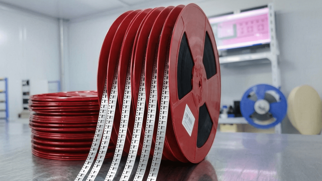
2.2 Key Material Parameters
Taking Kairuie Electronic Materials Co., Ltd.’s PC carrier tape as an example, typical parameters are as follows:
– PET Thickness: 0.30mm ~ 0.50mm (customizable based on component height)
– Adhesive Type: Heat-seal adhesive (heat-sealed for stable peel strength)
– Surface Resistance: Single-sided antistatic 10^6 ~ 10^9 Ω/sq, double-sided antistatic 10^6 ~ 10^9 Ω/sq
– Length per Reel: 300 meters/reel or 500 meters/reel
– Applicable Carrier Tape Materials: PC, PET, PS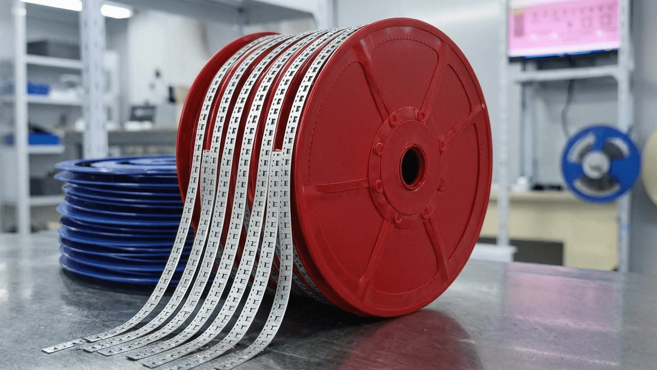
3. Core Process Parameter Control
3.1 Recommended Temperature, Pressure, and Time Ranges
For IC chip sealing processes, recommended parameters are as follows:
– Sealing Temperature: 160°C ~ 200°C (heat-seal adhesive activation temperature)
– Sealing Pressure: 0.2 ~ 0.4 MPa (avoid damaging components)
– Sealing Time: 0.5 ~ 1.5 seconds (adjust based on adhesive layer thickness)
Impact of each parameter on quality:
– Too low temperature leads to insufficient peel strength and loose components; too high may cause adhesive overflow or carrier tape deformation.
– Too low pressure results in weak sealing; too high may damage IC pins or solder balls.
– Too short time prevents full adhesive melting; too long expands the heat-affected zone.
3.2 Process Window Optimization Suggestions
It is recommended to determine the optimal process window through DOE (Design of Experiments). For IC chips, use medium temperature (180°C), medium pressure (0.3 MPa), and moderate time (1.0 second) as initial values, then fine-tune based on actual peel strength test results. The target peel strength range is typically 0.1 ~ 0.5 N (per EIA-481 standard).
4. Common Issues and Solutions
| Issue | Cause | Solution |
|---|---|---|
| Component Detachment | Sealing temperature too low or pressure insufficient | Increase temperature to above 180°C, increase pressure to 0.3 MPa |
| Excessive Peel Strength | Sealing temperature too high or time too long | Reduce temperature to 170°C, shorten time to 0.8 seconds |
| Static Residual | Antistatic layer failure or poor grounding | Check surface resistance value, ensure grounding system is normal |
| Carrier Tape Warpage | Uneven cooling or insufficient material temperature resistance | Optimize cooling airflow, select PC material (temperature resistance >140°C) |
| Component Misalignment | Inaccurate positioning from vibratory bowl feeder | Adjust vibratory bowl frequency or switch to tray feeding |
5. Quality Inspection Standards
5.1 Incoming Quality Control (IQC)
– Appearance: No scratches, bubbles, contamination; uniform color
– Dimensions: Width tolerance ±0.1mm, thickness tolerance ±0.02mm, sprocket hole pitch tolerance ±0.05mm
– Peel Strength: Per EIA-481 standard, peel strength 0.1 ~ 0.5N
5.2 In-Process Quality Control (IPQC)
– Sampling Frequency: 5 positions per reel (beginning, middle, end, and two intermediate points)
– Standard: Secure sealing, no warpage, no component misalignment, peel strength within range
5.3 Reliability Verification
– Aging Test: 85°C/85% RH, 1000 hours, peel strength change ≤20%
– Thermal Cycling: -40°C ~ 85°C, 100 cycles, no cracks or delamination
– Transport Test: Simulated vibration (10-500Hz) and shock (50g), no component detachment
6. Selection Recommendations
6.1 Recommendations by Component Type
| Component Type | Recommended Carrier Tape Material | Antistatic Level | Feeding Method |
|---|---|---|---|
| IC Chips (QFP/BGA) | PC | Double-sided Antistatic | Tray |
| Small ICs (SOP/SSOP) | PC or PS | Single-sided Antistatic | Tube or Vibratory Bowl |
| Resistors/Capacitors | PS or PET | Single-sided Antistatic | Vibratory Bowl |
| LEDs | PC | Double-sided Antistatic | Vibratory Bowl |
6.2 Selection by Application Scenario
– Small to Medium Batch Production: Recommend 300 meters/reel for flexibility and cost-effectiveness
– Automotive Electronics/Medical: Must use double-sided antistatic PC carrier tape to ensure reliability
– Compatibility with Multiple Sealing Methods: Kairuie PC carrier tape supports heat-seal and self-adhesive sealing, adaptable to different production lines
7. Conclusion
PC carrier tape, with its superior mechanical properties, temperature resistance, and electrostatic protection capabilities, is an ideal choice for IC chip SMT processes. Kairuie Electronic Materials Co., Ltd., deeply rooted in the SMT packaging field, offers high-quality PC carrier tape and customized solutions to help customers improve packaging yield and production efficiency. For more product information, please visit our official website: www.kairuie.com.cn. We look forward to exchanging ideas with industry peers to jointly advance electronic packaging technology.
